Your Contact for metal profile gaskets
Solid flat gaskets made of metal where soft materials are overwhelmed
Metal profile gaskets
Solid metal flat gaskets are used in areas where, due to the medium, temperature, pressure and/or permitted leakage rate, soft-material or metal/soft-material gaskets are not particularly suitable. They have proven reliable at low temperatures of -200°C as well as at high temperatures of over 600°C.
They are used at pressures ranging from relatively low to extremely high. The thickness of the seal and the sealing material are generally dependent on the flange surface and the operating conditions.
The better the flange surface in terms of surface quality and evenness, the thinner the gasket that can be used, e.g. 0.5 – 1 mm as a gasket in spinning nozzle fittings or 2 – 3 mm for aluminium gaskets in heat exchangers. It should be noted that soft metals (such as aluminium or silver) need only relatively low surface pressures to become deformed, harder materials on the other hand, particularly steel, require high sealing pressure.
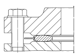
Gasket profiles


To reduce the sealing surfaces of gaskets with rectangular cross-section such as Profile A1, choose a convex crosssection shape. Information on this can be found in DIN 7603 at Form D. The absolute level of the sealing press capacity can be reduced by using narrow gaskets instead of wide gaskets or harder metals galvanised with thin overlays of soft metal.
Coatings of copper, nickel, silver or tin up to a maximum of 100 μm will give significantly better sealing properties and significantly lower deformation surface pressure σV . For the stated flange surface roughnesses a coating thickness of 35 to 50 μm is sufficient.
In metal profile gaskets, a line contact arises first. The bolt loads are clearly lower compared to metal flat gaskets (Profile A1). With the rectangular profile A1, even a slight flange twist can lead to sealing problems. The sealing diameter in the middle of the gasket jumps to the size of the external diameter, causing the leverage to be adversely affected.
The greater internal pressure also has a negative effect.
In convex gaskets on the other hand, the contact geometry is such that it is self-sealing at high internal pressures. The sealing diameter is retained and edge pressure is avoided.
Narrow gaskets are more heavily loaded at the same bolt force and can flow when insufficiently stable, leading to a loss of bolt load and leakages. To avoid flowing when loaded or even a destruction of the entire gasket, narrow flat gaskets should be chambered if necessary, as is the case with flanges with tongue and groove faces.
Even with a chambered specimen there can be damage to the gasket, particularly if the sealing material is sensitive to crevice corrosion. In this case, fitting in a groove can actually be disadvantageous. In order to prevent damage to the gasket, ensure that the maximum permitted surface pressure σϑ is not exceeded under any operating conditions.
Profiles A7 and H7 are centred by the corresponding shape of the flange e.g. male and female face joint. Gaskets of the type Profile H9 and H15 can also be used as high-pressure, high-temperature gaskets with flanges with raised or flat face flanges. The gaskets are then centred on the bolts. Profile H15, with a loose centring ring, is ideal for use with gaseous media and/or centring ring with widths greater than 15 mm. Profiles H7, H9 and H15 have an osculating radius R which is determined by the prevailing surface pressure.
Flat ring gaskets and other special shapes produced using special tools are also available. To protect from corrosion, galvanised overlays are possible. In copper gaskets with corrosion protection layers of hard nickel, the covering layer is only a few µm, so that the sealing properties are affected as little as possible by the harder protective layer.


Materials
1.0333, 3.0255, 2.0090, 2.4066, fine-grainsilver
Gasket limiting values: Profile A1
| Material | Iron (1.1003) RSt 28 (1.0326) | St 35 (1.0308) St 38.8 (1.0305) | 12CrMo 19 5 (1.7362) | 13CrMo 44 (1.7335) | X6CrNiTi 18 10 (1.4541) | X15CrNiSi 20 12 (1.4828) | Nickel Ni 99,6 (2.4060) Ni 99,2 (2.4066) | Cooper | Aluminium | Fine silver 99,98 Ag | ||
|---|---|---|---|---|---|---|---|---|---|---|---|---|
| Recommended max.roughness of the flange | µm | von bis | 1,6 3,2 | 1,6 3,2 | 1,6 3,2 | 1,6 3,2 | 1,6 3,2 | 1,6 3,2 | 1,6 3,2 | 3,2 6,3 | 12,5 25 | 6,3 12,5 |
| Surfaces pressurelimits for 20 °C | N/mm2 | σv σϑ | 235 525 | 265 600 | 400 900 | 300 675 | 335 750 | 400 900 | 190 510 | 135 300 | 70 140 | 50 160 |
| Surfaces pressure limits for 300 °C | N/mm | σv σϑ | 235 315 | 265 390 | 400 730 | 300 585 | 335 630 | 400 750 | 190 480 | 135 150 | – – | 50 135 |
Gasket limiting values: ProfileA7, H7, H9, H15
| Material | Iron (1.1003) | Heat-resistant mild steel 1.5415 | Heat-resistant mild steel 1.7362 | Stainless steel 1.4541 | Stainless steel 1.4828 | Steel St 35 copper-plated | Stainless steel 1.4541silverplated | Cooper 2.0090 | Monel 2.4360 | ||
|---|---|---|---|---|---|---|---|---|---|---|---|
| Recommended max. roughness of the flange | µm | von bis | 3,2 6,3 | 3,2 6,3 | 3,2 6,3 | 1,6 3,2 | 1,6 3,2 | 3,2 6,3 | 6,3 12,5 | 3,2 6,3 | 3,2 6,3 |
| Surfaces pressure limits for 20 °C | N/mm2 | σv σϑ | 235 525 | 300 675 | 400 900 | 335 750 | 400 900 | 135 300 | 100 750 | 135 300 | 260 660 |
| E modulus at 20°C | kN/mm2 | 210 | 210 | 210 | 200 | 200 | 210 | 200 | 128 | 178 | |
| Surfaces pressure limits for 300 °C | N/mm | σv σϑ | 235 315 | 300 585 | 400 730 | 335 630 | 400 750 | 135 390 | 100 630 | 135 150 | 260 650 |
| E modulus at 20°C | kN/mm2 | 185 | 185 | 190 | 186 | 186 | 185 | 186 | 114 | 175 | |