Your partner for metal jacketed gaskets
Proven in apparatus engineering – up to 550 ° C
Metal jacketed gaskets
Metal jacketed gaskets are proven sealing elements for use in apparatus construction, which are however increasingly being replaced at temperatures up to 550 °C by metal/soft-material gaskets, such as grooved gaskets.
At temperatures above 500 °C, such as in hot-blast areas, metal jacketed gaskets can still hold their own against solid metal gaskets such as weld ring gaskets.
Jacketed gaskets generally consist of a metal sheet coating with an insert of RivaTherm Super, graphite or FA1) or some layers of sheet metal. The metal sheet coating should be as soft and flexible as possible, but to prevent corrosion it is often made from a stainless steel jacket in 1.4541 or 1.4571 steel.
The harder the jacket, the finer the flange roughness needs to be. The inlay is selected according to the flange irregularities that need to be covered. The better the quality and the evenness of the sealing surfaces, the harder the inlay can be.
There is a wide range of possible combinations; the following are extremes at both ends:
- very soft: Coating of aluminium, inlay of graphite
- very hard: Coating of stainless steel, inlay of mica
Metal jacketed gaskets for heat exchangers are supplied with partitions in the model shown (picture 1).
Metal jacketed gaskets are also available as frames with rounded corners.
In flanges with tongue and groove or male and female face joints the jacketed gaskets should be fitted so that the tongue and/or the male face is against the smooth side of the gasket (picture 2).
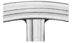
Pic 1 Profil F8
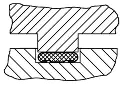
Pic 2
| Profile | Cross-section | Description |
|---|---|---|
| F2 |  | for flanges with raised face |
| F3 | for flanges with raised face | |
| F4 | for flanges with raised face | |
| F8 | for flanges with raised face, mostly used in apparatus construction | |
| F10 | mostly used in apparatus construction | |
| F12 | ||
| F17 | for flanges with raised face, Profile F17 produces lower bolt loads and more favourable deformation behaviour than Profiles F3, F4, F8 and FW3 | |
| FW3 | for flanges with raised face |
| Profile | Gasket limiting values | Aluminium & Graphite | Cooper, Brass & Graphite | Iron, Nickel & Graphite | Stainless steel & Graphite | Iron & Iron | ||
|---|---|---|---|---|---|---|---|---|
| F2 to F17 | Recommended max. roughness (RZ) of the flange surfaces | µm | from | 25 | 12,5 | 6,3 | 2,5 | |
| to | 50 | 25 | 12,5 | 6,3 | ||||
| Surface pressure limits for 20°C | N/mm² | σv | 30 | 60 | 70 | 100 | ||
| σϑ | 100 | 150 | 180 | 250 | ||||
| Surface pressure limits for 300°C | N/mm²ơ | σv | (40) | 70 | 80 | 115 | ||
| σϑ | (60) | 120 | 150 | 200 | ||||
| FW 3 | Recommended max. roughness (RZ) of the flange surfaces | µm | von | 6,3 | ||||
| bis | 12,5 | |||||||
| Surface pressure limits for 20°C | N/mm² | σv | 60 | |||||
| σϑ | 180 | |||||||
| Surface pressure limits for 300°C | N/mm²ơ | σv | 70 | |||||
| σϑ | 150 | |||||||
| F3L | Recommended max. roughness (RZ) of the flange surfaces | µm | von | 6,3 | ||||
| bis | 12,5 | |||||||
| Surface pressure limits for 20°C | N/mm² | σv | 200 | |||||
| σϑ | 500 | |||||||
| Surface pressure limits for 300°C | N/mm²ơ | σv | 200 | |||||
| σϑ | 350 |